Cookies on the OMEGA websites
We use cookies on this website, these cookies are essential for the website to work correctly.If you continue without changing your settings, we'll assume that you are happy to receive all cookies on this website.To find out more information about these cookies please click here.
CLOSE
Basket  |  Contact  |  Help  | 
Free Phone 0800 488 488
International+44(0) 161 777 6611
Layer N Banner

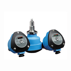
Thermal Dispersion Flow Switches

FSW-6000 and FSW-7000 Series

FSW6000-7000 series Thermal Dispersion Flow Switches | FSW-6000 and FSW-7000 Series

FSW6000-7000 series Thermal Dispersion Flow Switches

£771.32 FSW-6212

  • Simple to Install and Low Cost
  • No Moving Parts-Maintenance Free Reliability
  • Optimal Temperature Compensation — Unaffected by Temperature Gradient
  • Can Operate in Temperatures up to 120°C (248°F) with Sanitary Option
  • Have a Maximum Working Pressure of 4,300 PSI (300 bar)
  • Chain of 8 LEDs- Integrated Flow Rate/Setpoint Indication
  • Can Be Used as a Level Switch
Variable Area Flowmeters & Switches - View related products

Description

The FSW-6000/7000 Series are thermal flow switch monitors designed to monitor flow status and also used to detect level of liquids, air and gas. A chain of 8 LED’s gives the user a visual indication of the flow rate. In addition, there isalso a dichromatic LED, which shows the switch point status of the unit. The sensing element and connection of the FSW-6000/7000 Series are made with 316 SS. The standard enclosure is glass-filled nylon and is also available in an aluminum enclosure for hazardous environments. The FSW-6000/7000 Series can be made with a great variety of process connections such as threaded, flange, or sanitary.

The FSW-6000/7000 Series line of thermal flow switch monitors is based on the principle of thermal dispersion. A typical configuration uses two platinum Resistance Temperature Detectors (RTD’s) set within the tip of the sensor. One RTD is heated a few degrees above the temperature of the medium and the other RTD is used as a reference, sensing the actual process temperature. The second RTD also monitors the temperature of the medium, as any changes in temperature must be compensated for in the first RTD. As the process medium flows over the tip of the sensor it disperses some of theheat from the first RTD. The temperature change between the two RTD's signals the probe’s electronics and the switch changes state once the set point has reached.

The FSW-6000/7000 Series may be installed in a pipe or tank using the thread or connection provided. Use only the hexagon when tightening to achieve a seal, do not use the body. The body should be rotated after tightening to leave the cable gland in suitable orientation. The FSW-6000/7000 Series is not affected by its fixing position so it may be installed at any angle around the pipe. However, it is recommended that with horizontal pipe runs the sensor should be installed on the side, into the middle of the pipe. In vertical pipes, the FSW-6000/7000 Series should be installed when there is flow in an upward direction against gravity. Care should be taken when installing the sensor that the probe extends clear of the pipe’s internal wall and is fully immersed into the flow. In pipes with smaller diameters, some care should also be taken so that the sensor is not screwed too far into the line.

SPECIFICATIONS
Accuracy: ±10% of setpoint
Repeatability: ±1% of setpoint
Power Supply:
    FSW-6000: 85 to 240 Vac (50/60 Hz)
    FSW-7000: 24 Vdc ±10%
Temperature Range:
    Process: -20 to 80°C (-4 to 176°F) [sanitary option to 120°C (248°F) for CIP]
    Operating: -20 to 60°C (-4 to 140°F)
Max Pressure: 300 bar (4351 psi)
Protection Class: NEMA 4 (IP65)
Wetted Materials: 316 SS
Enclosure Material: Glass filled nylon standard or aluminum die cast option
Process Connection: ½ to 1½ NPT, Tri-Grip™, or flange (others available, consult Flow Engineering Department)
Output: 250 Vac SPDT 5 A relay
Switch Point Adjustment: Potentiometer
Bargraph:
    Green LED: Flow rate above setpoint
    Yellow LED: Flow is at above setpoint
    Red LED: Flow is below setpoint
Switch Point Status:
    Red LED: No flow
    Green LED: Flow
Response Time: 1 to 10 seconds
Max Start up Delay: 12 seconds
Switching Range: 3 cm/s to 3 m/s (0.09 to 9.84 ft/sec) (liquid), 5 cm/sec to 15 m/sec (0.16 to 49 ft/sec) (gas)
Dimensions:
    Nylon Head: 88 Dia x 80 mm H (3.5 x 2.5" H)
    Aluminum Head: 88 Dia x 108 mm H (3.5 x 4.25")
    Insertion Length: 138, 2 and 3" standard, for other lengths consult Flow Engineering
    Weight: Approx 680 g (1.5 lb)
Place Order(Specify Model Number)
Part Number/ Desc.
Qty
Description
Accessories
TX4-100
£44.79
Availability: In Stock
 
30 metre reel of 4-core screened cable
LP-PS-1524
Consult Sales  
Availability: 
 
 
DIN rail mount 24Vdc power supply. 15W, 0.63 Amp, 25mm wide. Powered by 85 to 260 Vac, 47 to 63 Hz
LP-PS-3024
Consult Sales  
Availability: 
 
 
24 Vdc, 1.5A power supply. DIN Rail mount. 85 to 260Vac powered
All amounts shown in EUR, GBP, or USD
Note: Comes complete with operator’s manual.
Ordering Example: (1) FSW-6212 Flow Switch, £771.32

Part Number Builder

Build Your Part Number Below
Option Descriptions:


(1) Power select from:
6 for 85 to 240 Vac
7 for 24 Vdc ± 10%

(2) Process Connection select from:
1 for 1/2 NPT thread
2 for 3/4 NPT thread
3 for 1 NPT thread
5 for 1-1/2" Tri-Grip
6 for 2" ANSI flange

(3) Enclosure select from:
1 for Glass filled nylon with 1/2 NPT conduit and cable gland
2 for Aluminum die cast with 1/2 NPT conduit
3 for Aluminum die cast with cable gland

(4) Insertion Length select from:
1 for 35 mm (1-3/8")
2 for 50 mm (2")
3 for 75 mm (3")
Note: All combinations may not be valid, check spec sheet for valid part numbers.
We noticed you are from the US. Visit your local site for regional offers and live support.