Cookies on the OMEGA websites
We use cookies on this website, these cookies are essential for the website to work correctly.If you continue without changing your settings, we'll assume that you are happy to receive all cookies on this website.To find out more information about these cookies please click here.
CLOSE
Basket  |  Contact  |  Help  | 
Free Phone 0800 488 488
International+44(0) 161 777 6611
Layer N Banner

RD9900 Series Paperless Recorder

RD9900 Series

RD9900 Series Paperless Recorder | RD9900 Series

RD9900 Series Paperless Recorder

£2,728.54 RD9906

CE
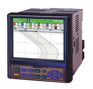
  • Employing Clear 5.6" TFT Color LCD Display
  • Large Capacity of Data Memory and Various Recording Method
  • Multi-Points Recording with High-Speed/ Accuracy
  • Easy Operating and Programming without Manuals
  • LAN Network Capability
  • Safety System and Reliability
  • Analyzing/Data Acquisition Application Software
Recorders - View related products

Description

RD9900 Series are network compatible paperless recorders with high performance and high operating function employed high visibility 5.6" TFT color LCD. High speed of sampling rate 100 ms for 12 points and high accuracy of ±0.1% were realized, and measured data is stored into internal memory and maximum 2 GB compact flash card. As it can be monitored by a web browser display on several computers on intranet or internet, FTP transfer of data file and e-mail notification are also available. The recorder can be used for various applications such as data management, research, development, remote and wide range monitoring by utilizing internet environment.

Input SPECIFICATIONS
Number of Measuring Points:
    RD9906: 6 points
    RD9912: 12 points
Input Types: Universal (refer to the table of inputs on page S-28, RD200/2800 Series)
Accuracy Rating:Refer to the table of inputs
Reference Junction Compensation Accuracy: K, E, J, T, N, Platinel II; ±0.5ºC or less; R, S, NiMo-Ni, CR-AuFe, WRe5-WRe26, W-Wre, U, L; ±1.0ºC or less
Sampling Rate: Approximately 100 ms for all points
Burnout: Disconnection of input signal is detected on thermocouple and resistance thermometer input; UP/DOWN disable is selectable for each input
Scaling: Range/scale is selectable when DC voltage/current is programmed
Digital Filter: Programming FIR filter for each point (common to all points)
Allowable Signal Source Resistance:
    Thermocouple Input (Burnout Disable)/DC voltage input (±2 V or less): 1 kO or less
    DC Voltage Input (±5 to ±50 V): 100 O or less
    Resistance Thermometer: Per wire 10 O or less (same resistance for 3 wires)
Input resistance: DC voltage, thermocouple input; approximately 1 MΩ
Maximum Input Voltage: DC voltage input (±2 V or less)/thermocouple input (burnout disable), ±10 Vdc
DC voltage input (±5 to ±50 V): ±60 Vdc
Dielectric Strength Between Channels: 1000 Vac or more between each channel (high strength semiconductor relay used)

DISPLAY SPECIFICATIONS
Display: 5.6" TFT color LCD
Display Types:
    Measured Data Display: Trend screen, data screen, bar-graph screen
    Historical Trend Display: Simultaneous display with real-time trend is available
    Information Display: Alarm display, marker list, file list
    Setting Screen: Alarm, computation, memory, system, maintenance, communication, etc.
Trend Screen: 12 colors selectable
    Display Screen: 5 screens (5 groups)
    Display Points: Maximum 44 points/screen/
    Time Axis Direction: Vertical or horizontal
    Line Width: 1/3/5 dot selectable
    Scale Display: 4 scales
    Tag/Data Display: Show/hide selectable Marker Display
Data screen: Display screen, 5 screens (5 groups)
    Display Points: Maximum 44 points/screen
    Display Contents: Measured value, channel/tag, unit, alarm status
Bargraph Screen: 12 colors selectable
    Display Screen: 5 screens (5 groups)
    Display Points: Maximum 44 points/screen
    Display Direction: Vertical or horizontal
    Scale Display: 1 scale
Information Display:
    Alarm Display: Alarm activation/released history display Marker List
    File List: Group data file list display
LCD Back Light: Auto/manual OFF function
LCD Brightness: 4 levels adjustment

RECORDING SPECIFICATIONS
Internal Memory: Flash memory, 4 MB capacity
External Memory: CF card, 32 MB to 2 GB capacity; 128 MB CF card is included as standard
Recording cycle: 100, 200, 500 ms*; 1, 2, 3, 5, 10, 15, 20, 30 s; 1, 2, 3, 5, 10, 15, 20, 30, 60 min
Numbers of Logging Files: 250/numbers of used groups
Logging Data: Measured data; file name (group name), time of day, month and year of recording start, tag, measured data, alarm status/types
Storing Types: Binary/CSV type
Storing Methods:
    Manual Start/Stop: Dedicated key operation
    Schedule: Designation for time of day and date
    Trigger Signal: Alarm event *Pre-trigger is selectable
Measuring Numbers of Pre-Trigger: Maximum 950 data
Recording Cycle*: Up to 3 groups of 12 points/group can be programmed for 100, 200 and 500ms recording; 5 groups of 44 points/group for recording with 1s or more (total of 100 points programming possible)

Recording Duration (CF Card):
When 6 channels recorded in sampling mode (real data)
Recording Cycle 128MB 256MB 512MB 1GB 2GB
0.1 sec 6.32 days 12.6 days 25.3 days 50.6 days 101 days
1 sec 63.2 days 126 days 253 days 1.4 yrs 2.8 yrs
60 sec 10 yrs 21 yrs 42 yrs 83 yrs 166 yrs

When 12 channels recorded in sampling mode (real data)
Recording Cycle 128MB 256MB 512MB 1GB 2GB
0.1 sec 3.16 days 6.32 days 12.6 days 25.3 days 50.6 days
1 sec 31.6 days 63.2 days 126 days 253 yrs 1.4 yrs
60 sec 5.2 yrs 10 yrs 21 yrs 42 yrs 83 yrs


COMPUTATION SPECIFICATIONS
Computation Points: Maximum 44 points
Computation Types:
    Arithmetic Operations: Addition, subtraction, multiplication, division, remainder, exponential
    Comparison Operations: Equality, inequality, great, less, equality/great, equality/less
    Logical Operations: AND, OR, XOR, NOT
    General Functions: Round-up, round-down, absolute value, square root, exponent of e, natural logarithm, common logarithm
    Integration Operations: Analog integration, digital integration
    Channel Data Operations: Measured data computation, calculated data computation

ALARM SPECIFICATIONS
Setups: Up to 4 alarms can be programmed per channel
Alarm Types: Upper limit, lower limit, differential higher limit, differential lower limit (deadband is selectable), abnormal data
Delay Function: Setup range of alarm delay, 1 to 3600 sec
Alarm Settings: AND/OR selectable

Communication Functions Network
FTP Server: Data file can be read from the network computer
Web Server: Conformed to HTTP1.0; displays the alarm, information of maintenance by browser software (Internet Explorer 5.0 or later, Net Scape 6.0 or later, Opera 7 or later) * User’s ID and password registration available
E-Mail: E-Mail notification at specified time for alarm activation; report data at specified time is selectable from all registered

USB COMMUNICATIONS
USB: Communication type, USB1.1
Transfer Systems: Bulk transfer, control transfer Communication Contents: File transfer by virtual drive connection
GENERAL SPECIFICATIONS
Rated Power Voltage: 100 to 240 Vac (universal power supply); 50/60 Hz
Maximum Power Consumption: 50 VA (DO: all points ON, 240 Vac)
Reference Operating Condition:
    Ambient Temperature/Humidity Range: 21 to 25°C, 45 to 65% RH
    Power Voltage: 100 Vac, ±1.0%
    Power Frequency: 50/60 Hz ±0.5%
    Attitude: Left/right 0°, forward/backward 0°
    Warm-Up Time: Longer than 30 minutes
Normal Operating Condition:
    Ambient Temperature/Humidity Range: 0 to 50°C, 20 to 80% RH
    Power Voltage: 90 to 264 Vac
    Power Frequency: 50/60 Hz ±2%
    Attitude: Left/right 0°, forward tilting 0°, backward tilting 0° to 20°
Transportation Condition (At the Packed Condition on Shipment from Our Factory):
    Ambient Temperature/Humidity Range: -20 to 60°C, 5 to 90% RH (note: no dew condensation)
    Vibration: 10 to 60 Hz, 0.5 G (4.9 m/S2) or less
    Impact: 40 G (392 m/ S2) or less
Storage Condition: Ambient temperature/humidity range -20 to 60°C, 5 to 90%RH (note: no dew condensation)
Power Failure Protection: Setups and data are backed up by flash memory
Clock: Lithium battery backs up RAM (minimum 5 years)
Insulation Resistance:
    Secondary Terminals and Protective Conductor Terminals: 20 MΩ or more at 500 Vdc
    Primary Terminals and Protective Conductor Terminals: 20 MΩ or more at 500 Vdc
    Primary and Secondary Terminals: 20 MΩ or more at 500 Vdc
Dielectric Strength:
    Secondary Terminals and Protective Conductor Terminals: 1 minute at 500 Vac
    Primary Terminals and Protective Conductor Terminals: 1 minute at 1500 Vac
    Primary and Secondary Terminals: 1 minute at 2300 Vac
Case Assembly Material:
    Door Frame: ABS resin
    Case: Steel
Color:
    Door Frame: Black (equivalent to Mussel N3.0)
    Case: Painting color, gray (equivalent to Mussel N7.0)
Weight: 2.2 kg (4.85 lbs)
Mounting: Panel mounting

OPTIONS SPECIFICATIONS
Name Contents
Alarm Output Relay contact ouput at alarm activation and abnormal input; output points: 12; contact capacity: mechanical relay, 100 Vac 0.5 A, 240 Vac 0.2 A
Communication Interface Communication interface for high-order instruments RS232C/RS485 switchable
*Ethernet and USB equipped as standard

Terminal Screws:
    Power Terminals/Protective Conductor Terminals/Communications Terminals: M4.0
    Measuring Input Terminals/Alarm Output Terminals/Remote Contact Terminals: M3.5
Place Order(Specify Model Number)
Part Number/ Desc.
Qty
Description
RD9906
£2,728.54
Availability: 16 weeks
 
6 points paperless recorder
RD9912
£3,689.68
Availability: 5 weeks
 
12 points paperless recorder
Option Boards
RD9900-C24
£556.57
Availability: 2 weeks
 
RS232C/RS485 communication interface
RD9900-AL12
£676.77
Availability: 2 weeks
 
12 point mechanical relay
Option Software
RD9900-ZAILA
£126.62
Availability: 2 weeks
 
ZAILA data analysis software
All amounts shown in EUR, GBP, or USD
Note: Comes with complete operators manual

Product Manuals:

Download RD9900 Series - Graphic Recorder Manual (2.95mb)
Download RD9900-Zalia - Zalia Software Instructions (4.6mb)
Download RD9900 Series - Graphic Recorder Manual (2.95mb)
Download RD9900 CF Card - CF Card Instructions
We noticed you are from the US. Visit your local site for regional offers and live support.