Temperature measurement with thermocouples?
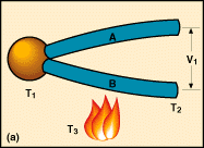
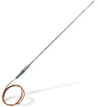
Thermocouple is probably the most-often-used and least-understood of the temperature measuring devices. Essentially, a thermocouple consists of two alloys joined together at one end and open at the other. The emf at the output end (the open end; V1 in Figure 1a) is a function of the temperature T1 at the closed end. As the temperature measurement rises, the emf goes up.
Often the thermocouple is located inside a metal or ceramic shield that protects it from a variety of environments. Metal-sheathed thermocouples are also available with many types of outer coatings, such as polytetrafluoroethylene, for trouble-free use in corrosive solutions.
The open-end emf is a function of not only the closed-end temperature (i.e., the temperature at the point of measurement) but also the temperature at the open end (T2 in Figure 1a). Only by holding T2 at a standard temperature can the measured emf be considered a direct function of the change in T1. The industrially accepted standard for T2 is 0°C; therefore, most tables and charts make the assumption that T2 is at that level. In industrial instrumentation, the difference between the actual temperature at T2 and 0°C is usually corrected for electronically, within the instrumentation. This temperature measurement adjustment is referred to as the cold-junction, or CJ, correction.
Temperature changes in the wiring between the input and output ends do not affect the output voltage, provided that the wiring is of thermocouple alloy or a thermoelectric equivalent (Figure 1a). For example, if a thermocouple is measuring temperature in a furnace and the instrument that shows the reading is some distance away, the wiring between the two could pass near another furnace and not be affected by its temperature, unless it becomes hot enough to melt the wire or permanently change its electrothermal behavior.
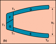
The composition of the junction itself does not affect the thermocouple action in any way, so long as the temperature, T1, is kept constant throughout the junction and the junction material is electrically conductive (Figure 1b). Similarly, the temperature measurement is not affected by insertion of non-thermocouple alloys in either or both leads, provided that the temperature at the ends of the "spurious" material is the same (Figure 1c).
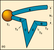
This ability of the thermocouple to work with a spurious metal in the transmission path enables the use of a number of specialized devices, such as thermocouple switches. Whereas the transmission wiring itself is normally the thermoelectrical equivalent of the thermocouple alloy, properly operating thermocouple switches must be made of gold-plated or silver-plated copper alloy elements with appropriate steel springs to ensure good contact. So long as the temperature at the input and output junctions of the switch are equal, this change in composition makes no difference.
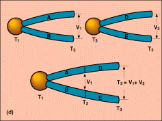
It is important to be aware of what might be called the Law of Successive Thermocouples. Of the two elements that are shown in the upper portion of Figure 1d, one thermocouple has T1 at the hot end and T2 at the open end. The second thermocouple has its hot end at T2 and its open end at T3. The emf level for the thermocouple that is measuring T1 is V1; that for the other thermocouple is V2. The sum of the two emfs, V1 plus V2, equals the emf V3 that would be generated by the combined thermocouple operating between T1 and T3. By virtue of this law, a thermocouple designated for one open-end reference temperature can be used with a different open-end temperature.
Temperature measurement using RTD
A typical RTD consists of a fine platinum wire wrapped around a mandrel and covered with a protective coating. Usually, the mandrel and coating are glass or ceramic.
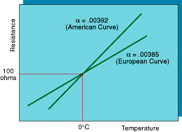
The mean slope of the resistance vs temperature measurement for the RTD is often referred to as the alpha value (Figure 2),alpha standing for the temperature coefficient. The slope of the curve for a given sensor depends somewhat on purity of the platinum in it.
The most commonly used standard slope for temperature measurement, pertaining to platinum of a particular purity and composition, has a value of 0.00385 (assuming that the resistance is measured in ohms and the temperature in degrees Celsius). A resistance vs temperature curve drawn with this slope is a so-called European curve, because RTDs of this composition were first used extensively on that continent. Complicating the picture, there is also another standard slope, pertaining to a slightly different platinum composition. Having a slightly higher alpha value of 0.00392, it follows what is known as the American curve.
If the alpha value for a given RTD is not specified, it is usually 0.00385. However, it is prudent to make sure of this, especially if the measures of themperature to be measured are high. This point is brought out in Figure 2, which shows both the European and American curves for the most widely used RTD, the Pt100 sensor, namely one that exhibits 100 ohms resistance at 0°C.
Temperature measurement using Thermistors
The resistance-temperature relationship of a thermistor is negative and highly nonlinear. This poses a serious problem for engineers who must design their own circuitry. However, the difficulty can be eased by using thermistors in matched pairs, in such a way that the nonlinearities offset each other. Furthermore, vendors offer panel meters and controllers that compensate internally for thermistors' lack of linearity. Thermistors are usually designated in accordance with their resistance at 25°C. The most common of these ratings is 2252 ohms; among the others are 5,000 and 10,000 ohms. If not specified to the contrary, most instruments will accept the 2252 type of thermistor.
Infrared temperature measurement devices
These tempeature measuring devices infer the amount of radiation emitted by a surface. Electromagnetic energy radiates from all matter regardless of its temperature. In many process situations, the energy is in the infrared region. As the temperature goes up, the amount of infrared radiation and its average frequency go up.
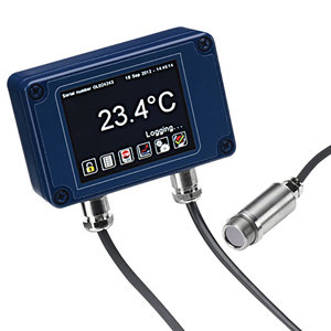
Different materials radiate at different levels of efficiency. This efficiency is quantified as emissivity, a decimal number or percentage ranging between 0 and 1 or 0% and 100%. Most organic materials, including skin, are very efficient, frequently exhibiting emissivities of 0.95. Most polished metals, on the other hand, tend to be inefficient radiators at room temperature, with emissivity or efficiency often 20% or less.
To function properly, an infrared temperature measurement device must take into account the emissivity of the surface being measured. This can often be looked up in a reference table. However, bear in mind that tables cannot account for localized conditions such as oxidation and surface roughness. A sometimes practical way to measure temperature with infrared when the emissivity level is not known is to "force" the emissivity to a known level, by covering the surface with masking tape (emissivity of 95%) or a highly emissive paint.
Some of the sensor input may well consist of energy that is not emitted by the equipment or material whose surface is being targeted, but instead is being reflected by that surface from other equipment or material. Emissivity pertains to energy radiating from a surface whereas reflection pertains to energy reflected from another source. Emissivity of an opaque material is an inverse indicator of its reflectivity Ð substances that are good emitters do not reflect much incident energy, and thus do not pose much of a problem to the sensor in determining surface temperatures. Conversely, when one measures a target surface with only, say, 20% emissivity, much of the energy reaching the sensor might be due to reflection from, e.g., a nearby furnace at some other temperature. In short, be wary of hot, spurious reflected targets.
An infrared device is like a camera, and thus covers a certain field of view. It might, for instance, be able to see a 1-deg visual cone or a 100-deg cone. When measuring a surface, be sure that the surface completely fills the field of view. If the target surface does not at first fill the field of view, move closer, or use an instrument with a more narrow field of view. Or, simply take the background temperature into account (i.e., to adjust for it) when reading the instrument.
Temperature measuring devices selection guide
Temperature measurements using
RTDs are more stable than
thermocouples. On the other hand, as a class, their temperature range is not as broad: RTDs operate from about -250 to 850°C whereas thermocouples range from about -270 to 2,300°C. Thermistors have a more restrictive span, being commonly used between -40 and 150°C, but offer high accuracy in that temperature range.
Thermistors and
RTDs share a very important limitation. They are resistive devices, and accordingly they function by passing a current through a sensor. Even though only a very small current is generally employed, it creates a certain amount of heat and thus can throw off the temperature reading. This self-heating in resistive sensors can be significant when dealing with a still fluid (i.e. neither flowing nor agitated), because there is less carry-off of the heat generated. This problem does not arise with thermocouples, essentially zero-current devices.
Infrared sensors, though relatively expensive, are appropriate when temperature measurements are extremely high. They are
available for up to 3,000°C (5,400°F), far exceeding the range of thermocouples or other contact devices. The infrared approach is also attractive when one does not wish to make contact with the surface whose temperature is to be measured. Thus, fragile or wet surfaces, such as painted surfaces coming out of a drying oven, can be monitored in this way. Substances that are chemically reactive or electrically noisy are ideal candidates for infrared temperature measurement. The approach is likewise advantageous in measuring temperature of very large surfaces, such as walls that would require a large array of thermocouples or RTDs for measurement.
 CLOSE
CLOSE

 Thermocouple is probably the most-often-used and least-understood of the temperature measuring devices. Essentially, a thermocouple consists of two alloys joined together at one end and open at the other. The emf at the output end (the open end; V1 in Figure 1a) is a function of the temperature T1 at the closed end. As the temperature measurement rises, the emf goes up.
  Temperature changes in the wiring between the input and output ends do not affect the output voltage, provided that the wiring is of thermocouple alloy or a thermoelectric equivalent (Figure 1a). For example, if a thermocouple is measuring temperature in a furnace and the instrument that shows the reading is some distance away, the wiring between the two could pass near another furnace and not be affected by its temperature, unless it becomes hot enough to melt the wire or permanently change its electrothermal behavior.
 This ability of the thermocouple to work with a spurious metal in the transmission path enables the use of a number of specialized devices, such as thermocouple switches. Whereas the transmission wiring itself is normally the thermoelectrical equivalent of the thermocouple alloy, properly operating thermocouple switches must be made of gold-plated or silver-plated copper alloy elements with appropriate steel springs to ensure good contact. So long as the temperature at the input and output junctions of the switch are equal, this change in composition makes no difference.
 The mean slope of the resistance vs temperature measurement for the RTD is often referred to as the alpha value (Figure 2),alpha standing for the temperature coefficient. The slope of the curve for a given sensor depends somewhat on purity of the platinum in it.
  The resistance-temperature relationship of a thermistor is negative and highly nonlinear. This poses a serious problem for engineers who must design their own circuitry. However, the difficulty can be eased by using thermistors in matched pairs, in such a way that the nonlinearities offset each other. Furthermore, vendors offer panel meters and controllers that compensate internally for thermistors' lack of linearity. Thermistors are usually designated in accordance with their resistance at 25°C. The most common of these ratings is 2252 ohms; among the others are 5,000 and 10,000 ohms. If not specified to the contrary, most instruments will accept the 2252 type of thermistor.



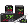


 Medición de Temperatura
 Medición de Temperatura
 Temperature Measurement
 Temperaturmåling
 Introduction à la mesure de température
 Temperaturmessung
 Temperature Measurement
 Sensor de temperatura
 Temperature Measurement
 Temperature Measurement
 温度測定
温度測定 Temperature Measurement
 温度测量
温度测量 온도 측정
온도 측정 Temperature Measurement
 Temperature Measurement
 Temperature Measurement
 Temperature Measurement
 Temperature Measurement